Pathways: Google's New ML System
Google recently released the paper about its new ML system called Pathways. I’m a bit surprised since I expect it to introduce a brand new model architecture. In fact, this paper is not easy to digest at all. I feel like it’s written for people who spent many years developing ML frameworks. Anyway, we will try to understand why it is developed and how it works. Also, you should check this post (in Chinese). This post explains many concepts in Pathways much more clearly. Many contents here are credited to this post.
This paper spends a long time discussing single-controller and multi-controller. It’s really confusing to understand all these SPMD, MPMD, single-controller, and multi-controller stuffs. Pathways claims the future ML framework should go back to single-controller. By “back” I mean ML frameworks were originally single-controller, then they adopted multi-controller. Now, we are going back to single-controller again.
Single-Controller
TensorFlow v1 is a classic example of single-controller system. The high level idea is the user would define a dataflow graph through a Python client. This graph is then submitted to the session.run (runtime system). The system consists of a single master and many other workers. The mater will compile and the dataflow graph submitted by the client, then divides the graph into sub-graphs. Then the master submits those subgraphs to other workers.
In this case, each worker computes its own share of sub-graph. The client + master are the controller.
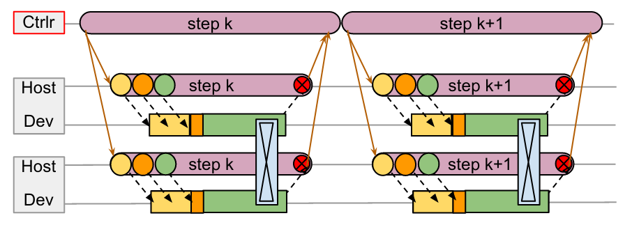
As the paper suggests, dispatching computations in a single-controller system requires communnication across (data center network) DCN. All the orange lines are control messages flowing through DCN. We can see the workers are idle for a long time between each step, even though there’s no gap between adjust steps on the controller.
The controller submits jobs to all workers in each step, then waits all workers to finish computing their own sub-graphs. The problem is: 1) waiting for all workers to finish computation in a lock-step fashion is inefficient; 2) send and wait for control messages (orange line) is costly since these messages go through slow DCN.
Multi-Controller Systems
Contrary to single-controller systems, multi-controller systems like Jax adopts a different philosophy. Under multi-controller systems, each worker shares the same code and executes different stage/branch of the code. This is why they are called SPMD systems (single-program-multiple-data).
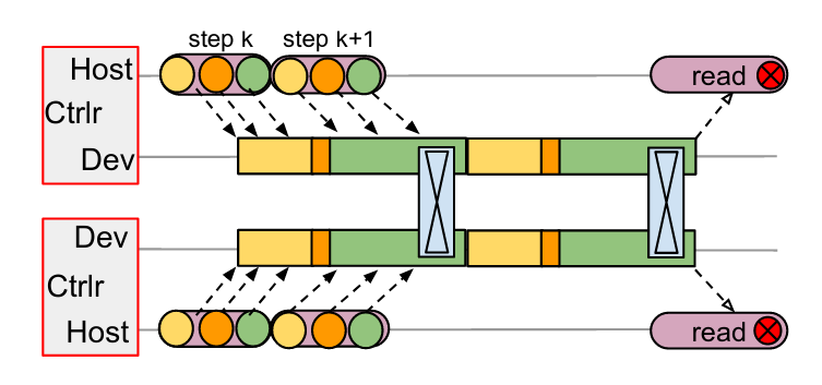
Take MPI process as an example, every MPI process is an entrance (client) to the program (In single-controller systems, only the client-master can be the entrance).
Since multi-controller systems doesn’t have a centralized coordinator, all workers in can initiate communication with each other, using much faster channels such as PCIe or NVLink. In the multi-controller graph, the black dotted lines represents message between hosts and devices (through PCIe); the communication between devices happens through fast NVLink. So we don’t have the big overhead introduced by DCN.
If you want to get a taste of how PyTorch vs TensorFlow v1’s (multi-controller vs single-controller) programming style feels like, here are two examples: Writing Distributed Applications with PyTorch and End-to-End Tutorial for Distributed TensorFlow 1.x.
Going Back to Single-Controller
We could stick with multi-controller systems forever. If every worker node shares symmetric workloads and communications (like all-reduce, all-gather, etc.), then there’s nothing to be worried about. After all, multi-controller seems much more efficient than single-controller based on what we’ve discussed so far.
However, pipeline parallelism changes the story. Under pipeline parallelism, different workers in the pipeline will execute at different programs. Thus we have MPMD (multi-program-multi-data). For example, we can have one worker doing convolution for batch 1 while another worker is doing encoding work on batch 2. At each stage of the pipeline, the worker is doing different jobs on a different data batch (think of a CPU pipeline where each stage is executing different instructions).
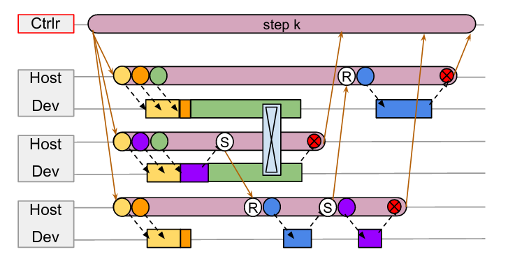
Take the above graph as an example, assume we have three workers 1, 2, 3 from top to bottom. Each worker is performing asymmetric workloads and doing irregular point-to-point communications (instead of symmetric communications like all-gather). Obviously, multi-controller doesn’t fit into this kind of workload. How do you write a single copy of code that does all these irregular communications under multi-process scenarios?
Thus, Pathways proposes we should go back to single-controller, so that we can let the master node handle all these nasty communication patterns.
Deadlock
Single-Controller brings back gang-scheduling and centralized coordinator. The reason to use gang-scheduling and centralized coordinator is to help preventing deadlocks. However, the rational behind this design decision is hard to interpret from reading the paper. I’m going to use the post from Jinhui Yan (the developer behind OneFlow) to explain why gang-scheduling and centralized coordinator prevent deadlocks.
Gang-scheduling is essential in the case of TPUs, since they are single-threaded and only run non-preemptible kernels, so the system will deadlock if communicating computations are not enqueued in a consistent order.
We can think of a computing device as a FIFO task queue (e,g. CUDA streams, TPU, or CPU…). Each FIFO task queue essentially have a stream of tasks to process.
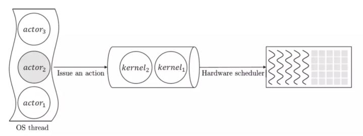
The paper emphasizes that TPUs are single-threaded and only run non-preemptible kernels. That means we can think of each TPU as a single FIFO task queue. Once we enqueue a task, it can not be preempted from the queue. We need to wait until this task finishes its computation before we can execute the next task in the queue. This is a problem!
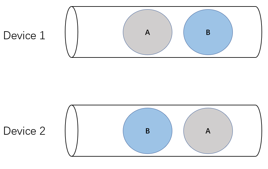
Imagine we have two devices (1 and 2), represented as two FIFO queues. Device 1 chooses to enqueue task A first and then B; device 2 decides to enqueue task B first and then A. Both tasks A and B are performing an all-scatter operation. Therefore, task A on device 1 needs to wait for messages from task A on device 2. Similarly, task B on device 2 needs to wait for messages from task B on device 1.
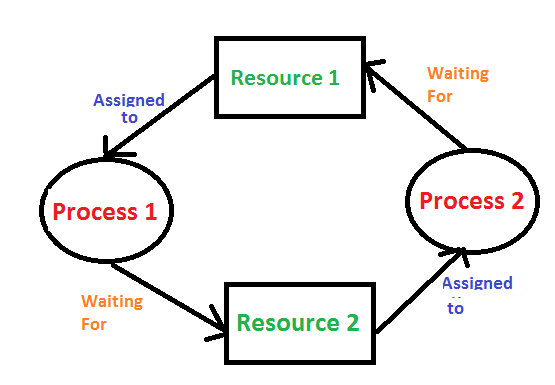
This is a classical example of deadlock in operating systems.
Solutions to Deadlock
Using gang-scheduling helps preventing deadlocks, because it enforces a global enqueueing order across multiple FIFO queues, instead of letting each queue handling tasks separately.
The paper also mentions allowing device (e.g. GPUs) to execute tasks concurrently can prevent deadlocks. This is because concurrency eliminates the non-preemption property which is required for deadlocks to happen.
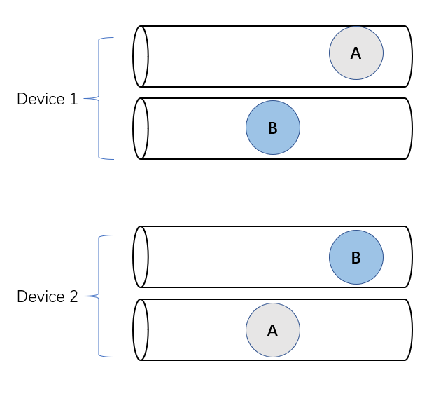
If each devices allows concurrency executions (each device has multiple queues), then the task on one queue can be preemptied to allow the other task start executing, thus no deadlock (this is not strictly the case, the post explains an interesting scenario in NCCL where deadlocks can still happen if there are too many communications).